Digitizing machines – Add machine

Select “Show Details” for the node to which you want to add a new machine.
To add a new machine, we click Add Machine.
A dialog for adding a machine opens. This guides you through the simple connection in eight steps. Among other things, MDC/DNC controls are configured and machine signals are defined here.
Step 1 Select template
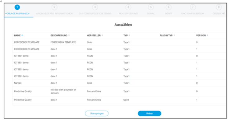

Multiple machines of the same type do not have to be completely reconfigured each time in FORCE EDGE CONNECT: Once a machine has been configured, it can be entered as a template in the MachineRepository and will then be offered in this mask the next time a machine is connected.
- If the template is selected here, all settings are automatically applied to this machine and all non-machine-specific configuration fields are pre-filled.
- Only machine-specific (e.g., serial number) and connection-specific information (e.g., IP address or port of the machine or controller) must still be adapted.
The template VERSION indicates which version it has. If a template is revised, the version number is automatically incremented and the previous version is overwritten. Version 0 means that no script is configured in the corresponding template.
Attention This step is only available if the MR component is used. If no template is configured or MR is not in use, the machine connection starts with step 2
- If a suitable template is available, you can select it and continue with step 2 or choose Skip if no suitable template is available.
- When a step is completed, it is highlighted in blue in the top bar. Clicking on a completed step returns you to that step.
Step 2 Basic information
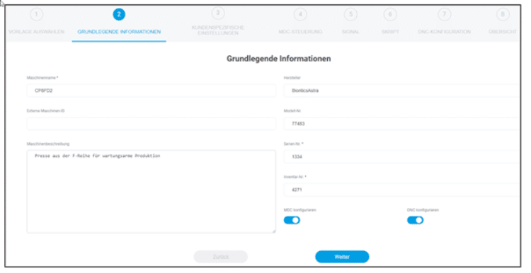
Basic information of the machine to be configured, such as name or serial number, is entered here.
Here it is also determined whether an MDC or a DNC control is to be configured – or both. You can set this with the corresponding switches.
With the MDC controller, signals are fetched from the machine and passed on or written to it. NC files are transferred to the machine via the DNC controller
Step 3 Custom settings
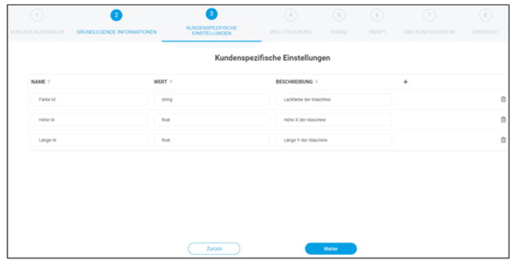
In step 3, you have the option to store individual, plant-specific information for a machine with the purpose of additionally enriching machine data. This data can later be retrieved from the API to provide more information to a third-party system.
With a click on the add symbol, you can add new data.
For example: Name = Location, Value = Hall 2. Here, an additional local aspect is given to the machine data in order to precisely locate the machine in the event of a malfunction. Step 3, however, is completely optional.
Step 4 MDC control
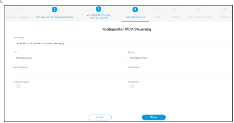
This step offers the possibility to configure an MDC controller. This step is logically only available if you have configured MDC in step 2.
This is where the way in which the machine is to be connected is determined. FORCAM supports all common controllers on the market and constantly strives to expand their availability. An overview of the current FORCAM plug-ins can be found in the documentation.
Let’s take a closer look at the fields:
- You can optionally enter the description of the control
- Then select the control type. In the drop down menu you will see all available control types.
- In our example we use a Siemens S7 300.
- In our example we use the FORCAM IO controller.
Depending on the selected type, additional configuration parameters appear.
Next we select the bus type. The selection option depends on the previously selected control type.
Finally, we adjust the controller-specific configuration and then click on continue.
Step 5 Signal definition
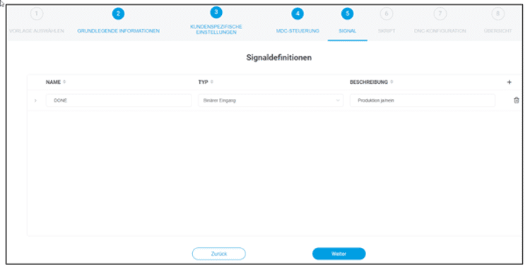
Here you define which signals are read from the controller. For example, to allow the interpretation “Machine running” or “Machine not running”, a binary signal can be configured. If 1 is signaled, the machine is in production; if 0 is signaled, it is at a standstill. In this example, the signal is called “DONE”. Production Machine On
In addition, different data types can be used to map various signals such as temperature.
Signals can also be defined that can be written to the controller, e.g. an order number or default times.
The signals to be used depend, among other things, on the use case, the controller, and the possibilities of the machine.
To create a signal
Click on the add icon
Enter a name and type. Click the signal and enter the desired parameters and a description.
Set the slide switch to Active and click Next.
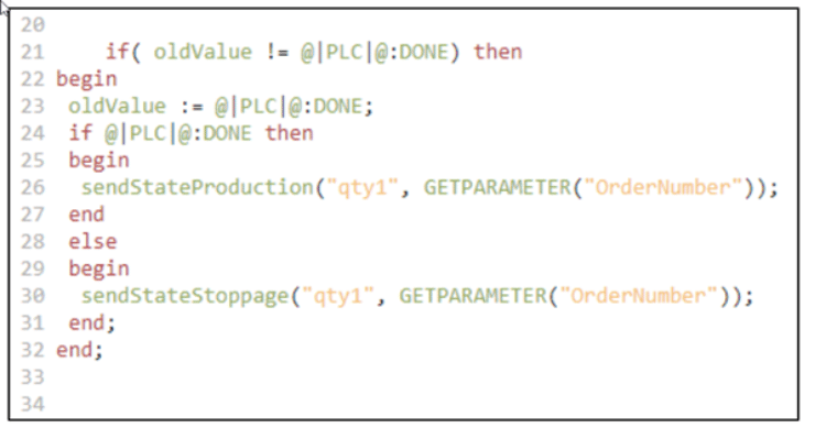
Step 6 Script
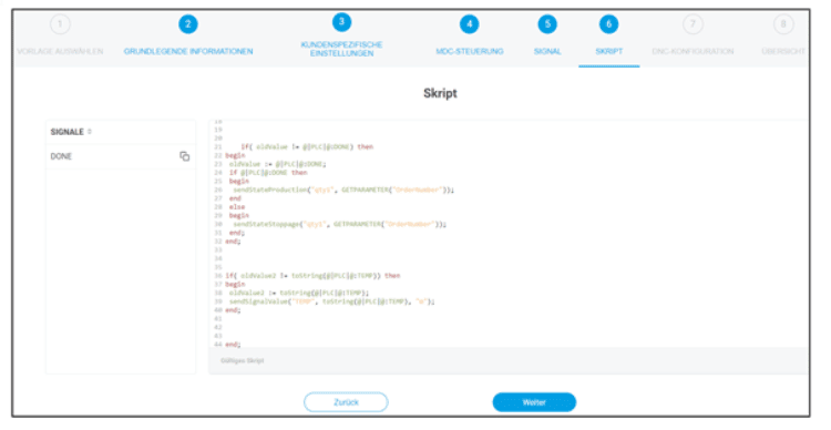
The script determines how the machine signals are to be interpreted. Depending on the control, different signals can be read out by a script, e.g. “Production in semi-automatic state” or “Standstill due to mechanical error”.
In the left area of the mask all signals configured in step 5 are listed. The central area in the middle is the input field for a script, where the actual machine logic is defined.
The script is structured as follows to follow the example of the “DONE” signal from step 5, the:
If bit 1 for “DONE” is received from the machine, a sendStateProduction event is sent, which ultimately corresponds to the production status. If no bit flag is set to 1, sendStateStoppage is sent, i.e. standstill.
Further script examples can be found in the documentation.
To configure a script: Select the signal you want to assign a script in the left pane.
And enter the desired script in the central input field.
Optionally, the script can be run using the play icon at the top right to check validity.
If everything is ready, click Next.
Step 7 DNC Configuration
Step 7 is only available if DNC was activated in step 2. Here the way in which an NC file is to be transferred to the machine is determined.
FORCAM supports all common controllers on the market and is constantly striving to expand the availability. An overview of the current FORCAM plug-ins can be found in the documentation.
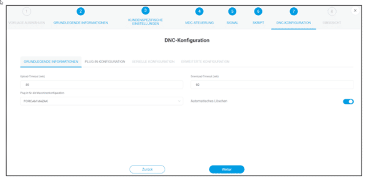
The basic information like upload and download timeout is optional.
Select the plug-in for the machine configuration. Further configuration parameters are entered in the remaining tabs depending on the selected plug-in.
Automatic deletion is also optional. If the switch is activated, the NC file is automatically deleted after reading from the machine.
Step 8 – Overview
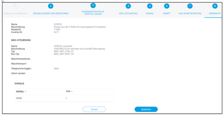
Here the previous configuration from all steps is summarized and all defined signals are listed. After confirmation, the machine is mapped with the specified configuration and thus digitized.
The configured machine appears under the defined name in the overview.